
Overview
- Cura can be used to prepare files for almost all FDM printers.
- For a printer to understand a STL file, it needs to be prepared using a "Slicer" - software, which converts the geometry into a long series of coordinates, which the printer can understand.
- Ultimaker provides their own, open-source software called Cura.
- Download from: https://ultimaker.com/en/products/cura-software
- Select the correct printer if this is the first time the software is being used: Machine -> Add new machine...
- A full documentation for Cura can be found here. In the following, we will introduce the features that we use and find useful.
- Slicers only control how an extrusion printer head moves! How much material is being extruded (and at what diameter) depends on the extrusion nozzle and its temperature.
Navigation
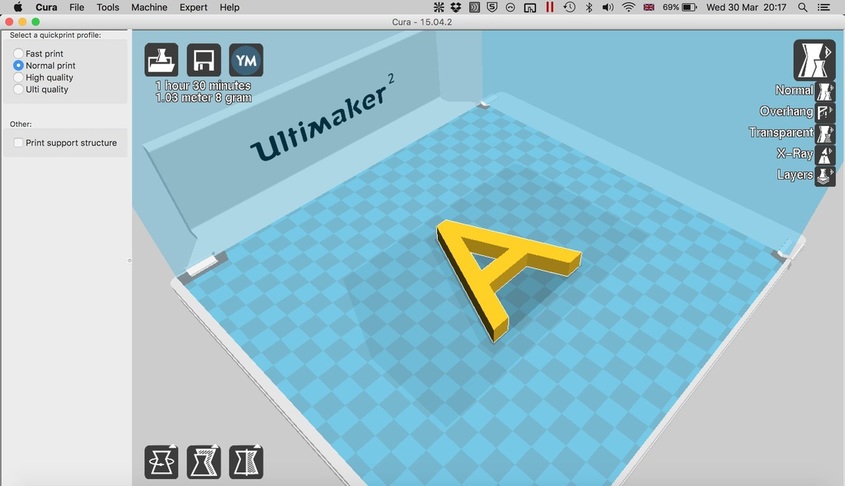
- Open the file using the folder button (top left).
- Optional: select a quickprint profile on the left for an easy setup. For more flexibility see "Options".
- Click on object to enable Rotate/Scale/Mirror (bottom left). Drag and drop to position object.
- Zoom with mouse wheel. Ctrl+Drag to rotate view. Ctrl+Shift+Drag to pan the view.
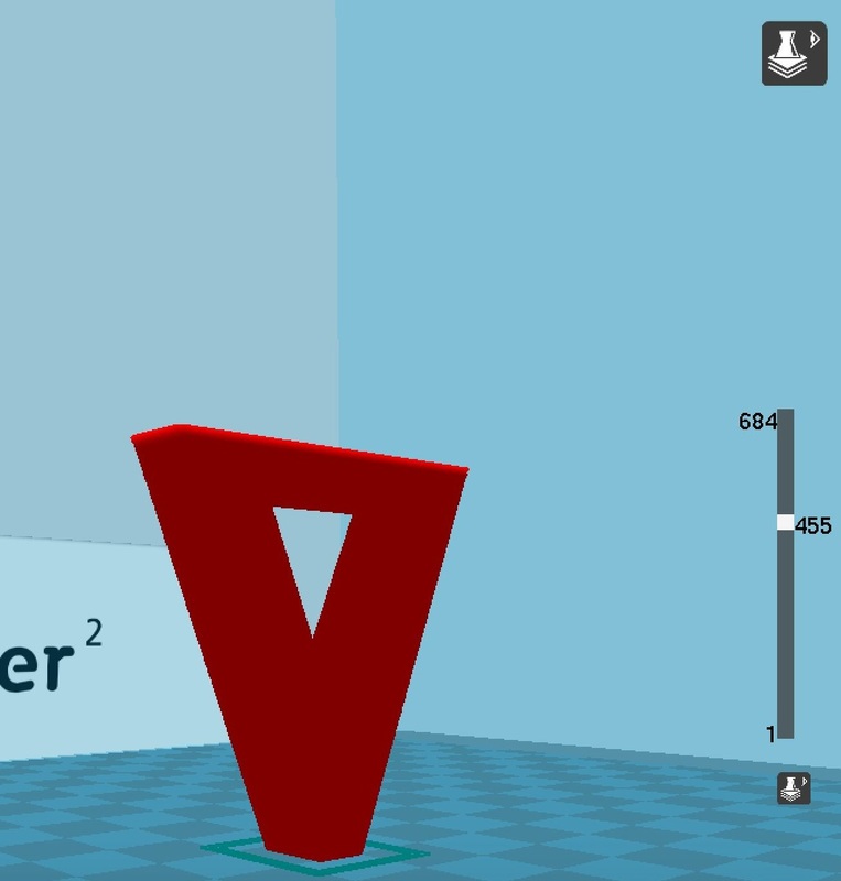
- Use the view options on the top right to ensure that the object will be printed as intended (See "The Views" and "The Layers View").
- Click the save button (top left) to export the .stl file to .gcode. This filetype can be read by many printers, including Ultimakers!
The Views
- Aside from the normal view, there are four other ways of rendering the object:
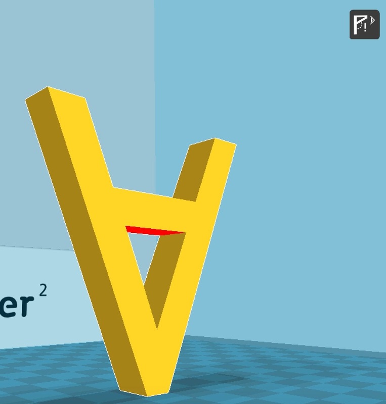
- Overhang: Overhanging surfaces are highlighted in red.
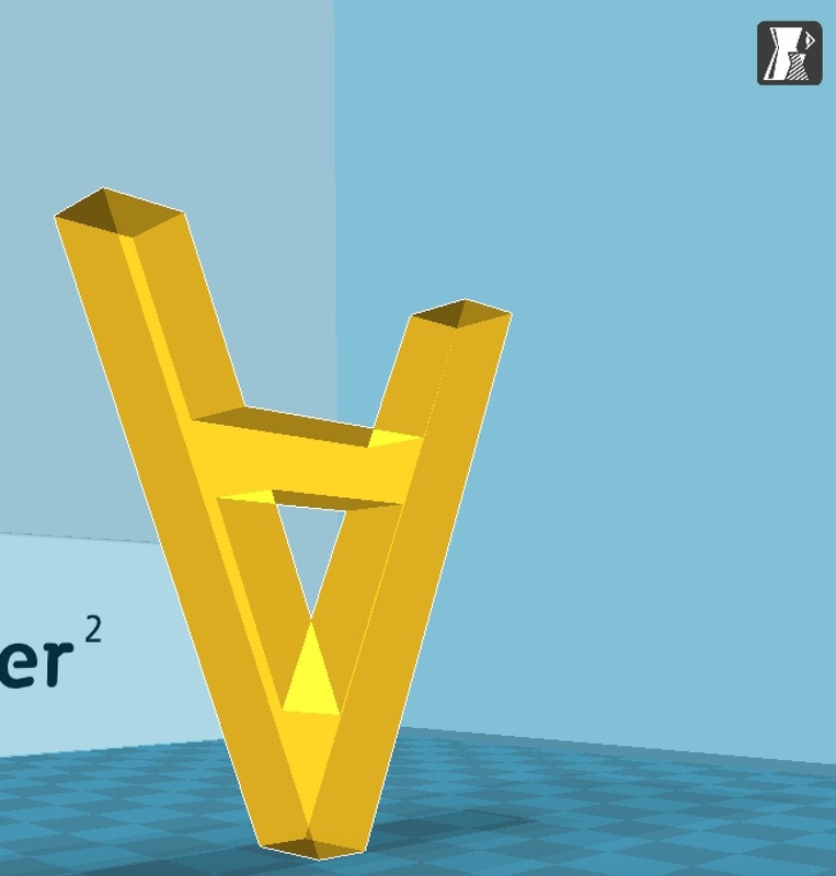
- Transparent: Use this to inspect internal structure.
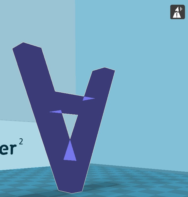
- X-Ray: This can be used to highlight broken geometry.
- Layers: This traces out the path the print nozzle will follow during the print. This is the most import part of ensuring the printer will do what you want it to! (See "The Layers View")
|
|
|
|
The Options
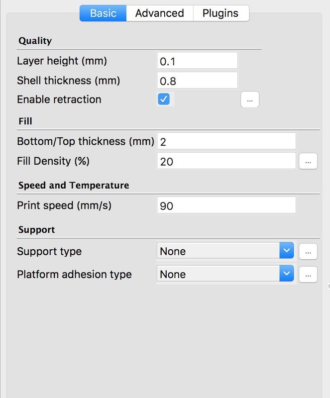
- Enable full setting for more control over your print: Expert -> Switch to full settings...
- Hover your mouse over each option to see tooltip with a short explanation and typical values.
- All the basic options are important and you should read the their tooltips!
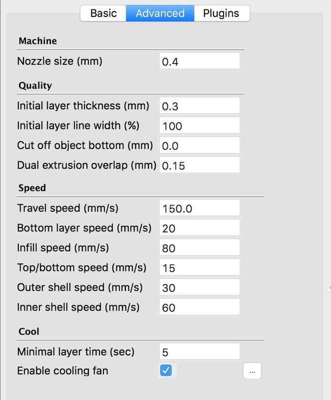
- We usually leave the advanced options at their default values. Don't mess with them if you are a beginner.
- We like to keep "Shell thickness" a multiple of "Nozzle size". The factor defines the number of outer layers.
- "Layer height" and "Print speed" are the key parameters to control duration and quality of print.
- Fill Options: keep the fill density and bottom/top thickness as low as possible unless you need a specific value (0.6 and 20 are usually sufficient). You can turn top and bottom infill off.
- Support is essential if you have overhangs.

|
|
|
|
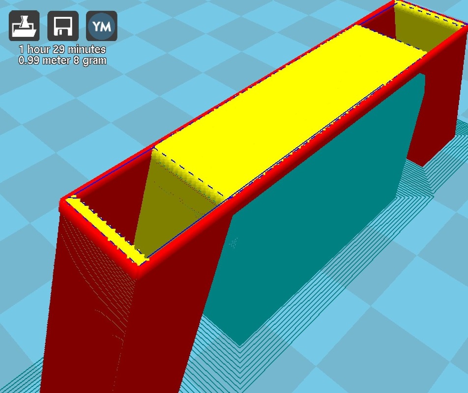
The Layers View
- Red = Outer shell
- Green = Inner shell
- Yellow = Fill
- Cyan = Support
- Blue = Travelling Nozzle (no extrusion, but stringing is possible!)
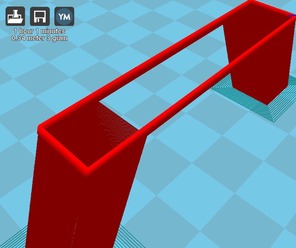
1. No Support, No Fill, Shell thickness = Nozzle size.
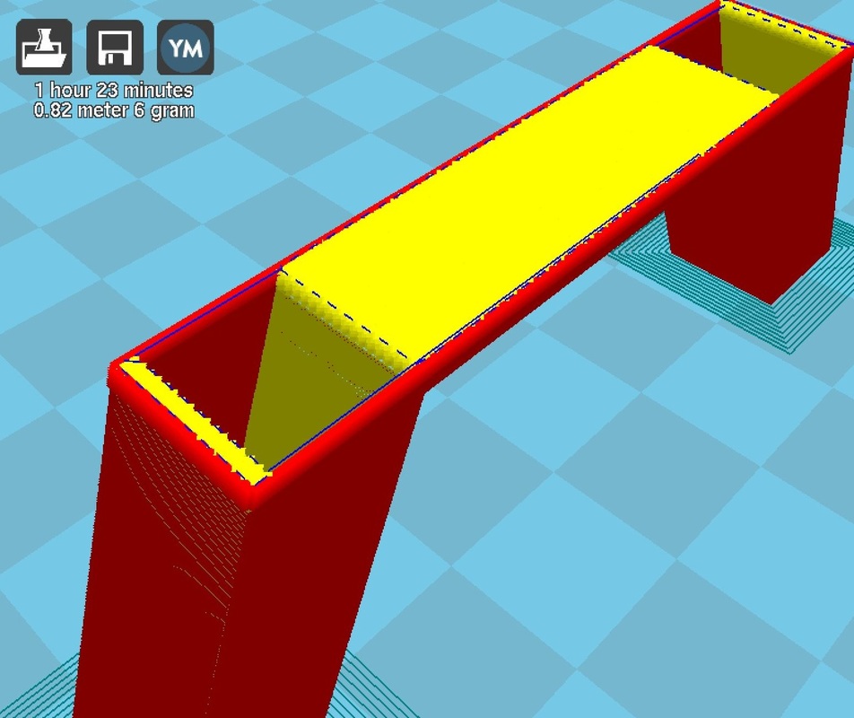
3. Support turned on. Essential for a large overhang like this.
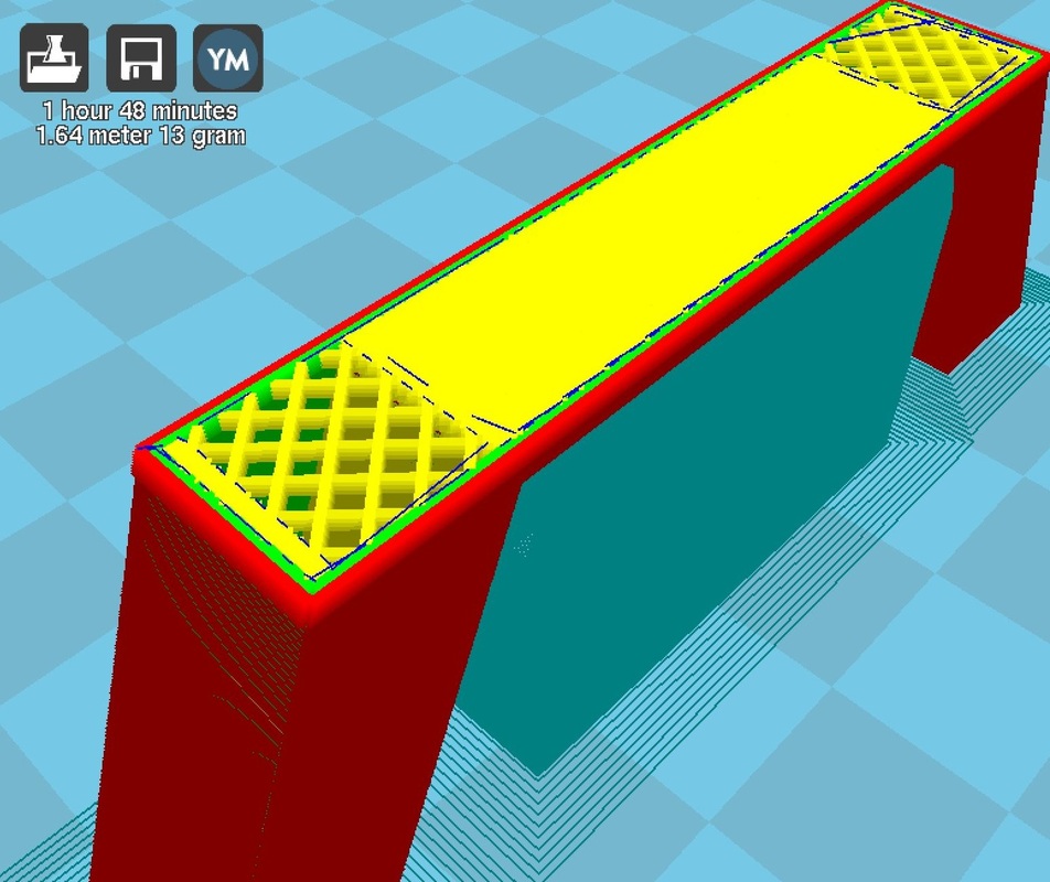
5. Fill density turned on. Useful for a stronger object.
|
2. Bottom Infill turned on. Notice the thicker shell on the sides!
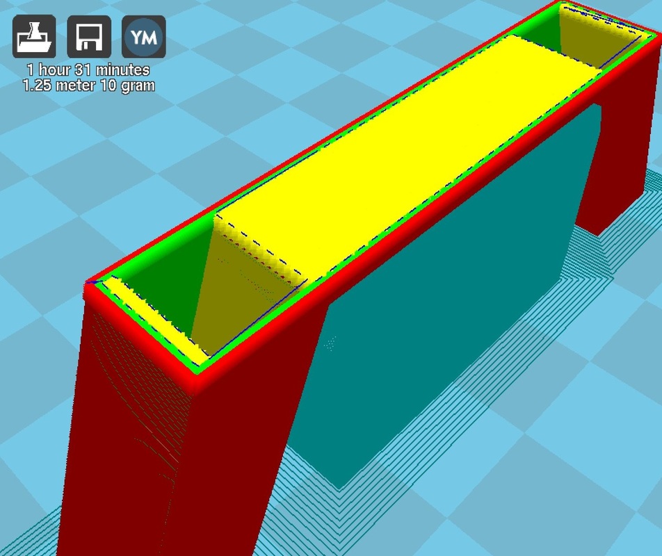
4. Shell thickness = 2 x Nozzle size. A second layer appeared.
|
Print Faults
- Stringing: When the print head moves outside the print, some plastic gets extruded. Reduce the nozzle temperature and travel speed to combat this.
- Overhangs: The left hand "A" model below was printed without support, but the large overhang still printed fairly well. However, overhanging surfaces have a bad finish.
- Under-extruded layers: The left "B" model has regions where not enough plastic was extruded. Reduce the print speed to combat this.
- For a more in depth discussion on printing faults, check out http://support.3dverkstan.se/article/23-a-visual-ultimaker-troubleshooting-guide
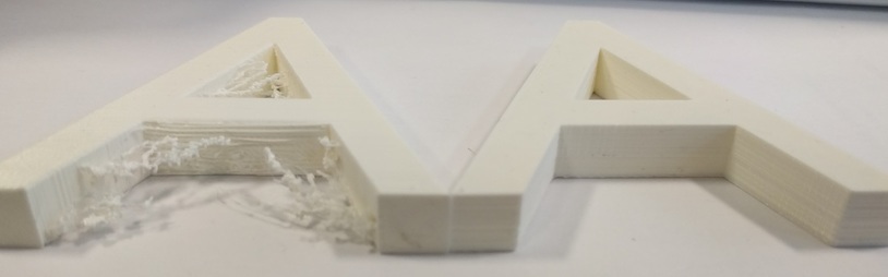
The left "A" was printed standing upright, the right "A" was printed lying flat.
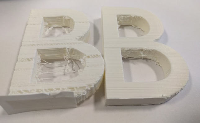
The left "B" has a layer thickness of 0.25mm, the right "B" has a layer thickness of 0.08mm.