
1. From the Osirix website, download the ARTIFIX dataset http://www.osirix-viewer.com/datasets/
2. Run 3D slicer (Download from https://www.slicer.org/)
3. Import the DICOM data (DCM > Import > Select directory ‘Aorta w/c 1.5 B20f 60%’ > Import > Copy > OK)
2. Run 3D slicer (Download from https://www.slicer.org/)
3. Import the DICOM data (DCM > Import > Select directory ‘Aorta w/c 1.5 B20f 60%’ > Import > Copy > OK)
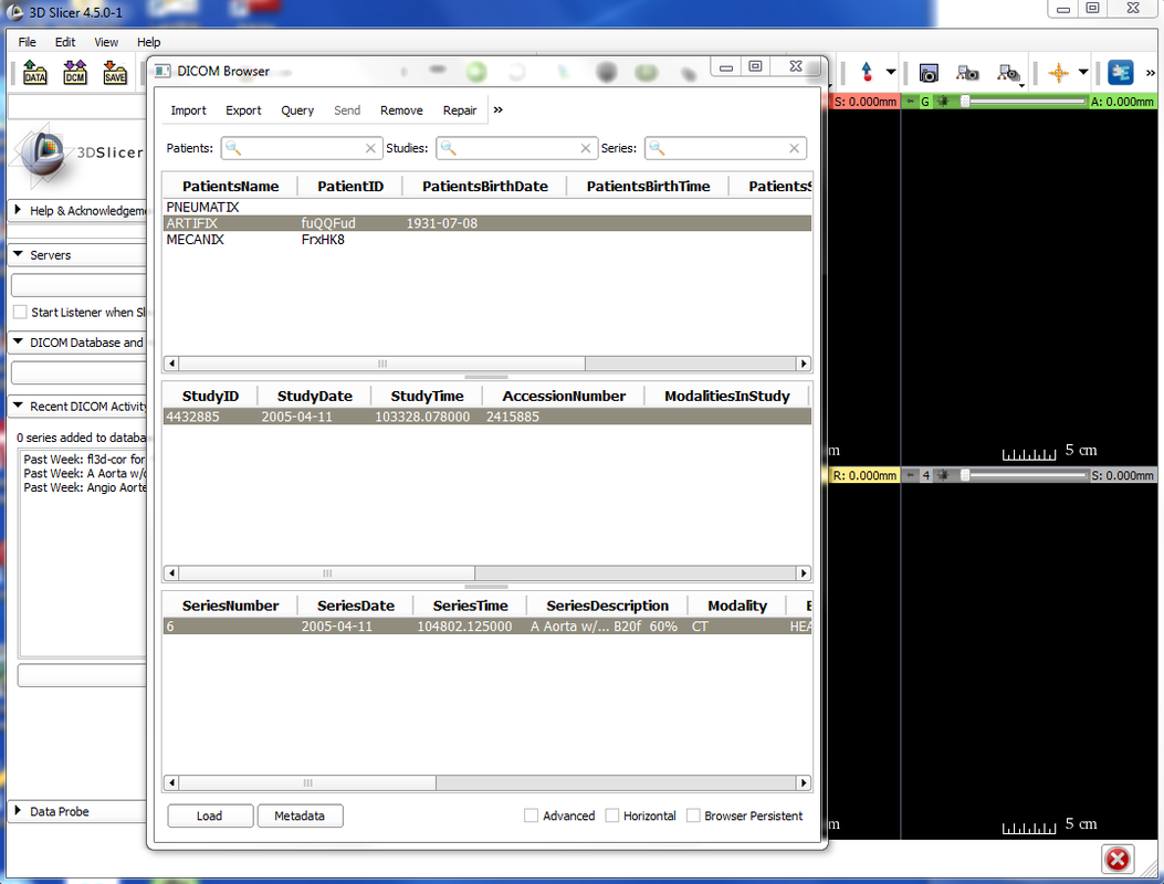
4. Load the DICOM data into the scene (DCM > Import > Select data > Load)
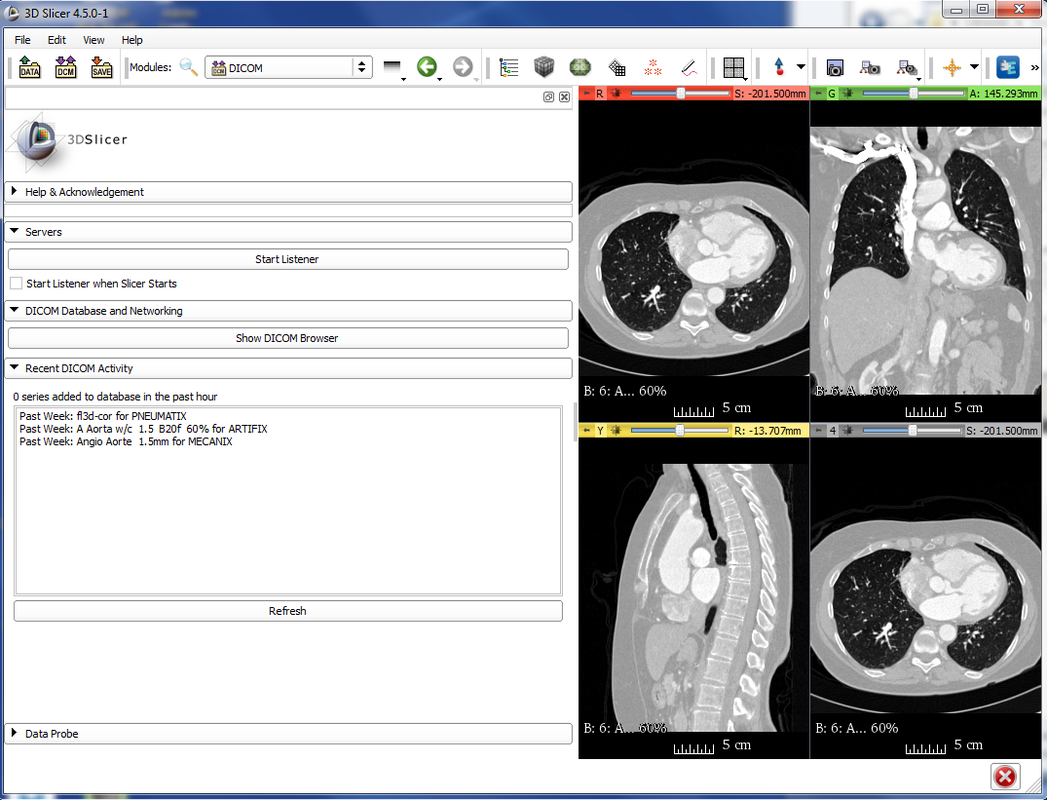
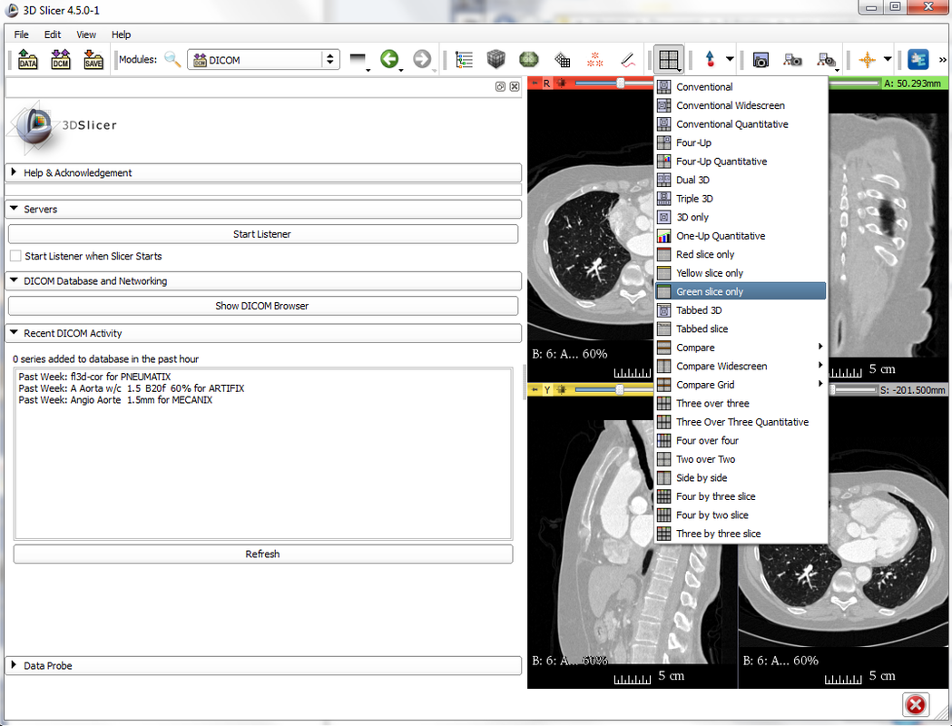
5. The default setting is to have four views of the data. You can scroll through the slices using the sliders above each view. For segmentation, it’s easiest to just see one view, so select the grey squares icon on the taskbar and set the view to Green slice only
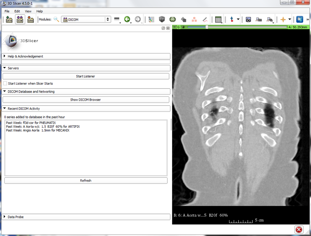
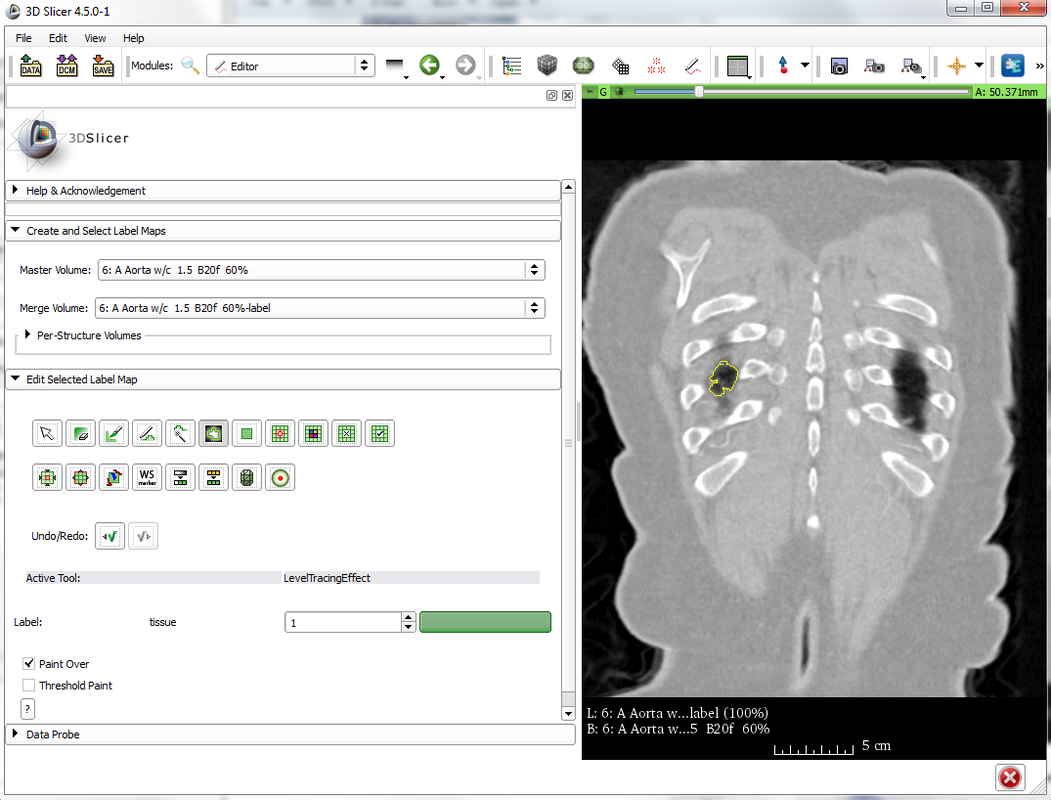
6. Scroll through the slices using the slider at the top of the view. We are going to be segmenting the lung on the left hand side of the view (this is actually the right lung). Find the slice at which the lung first becomes visible (A: 50.371mm in the top right corner)
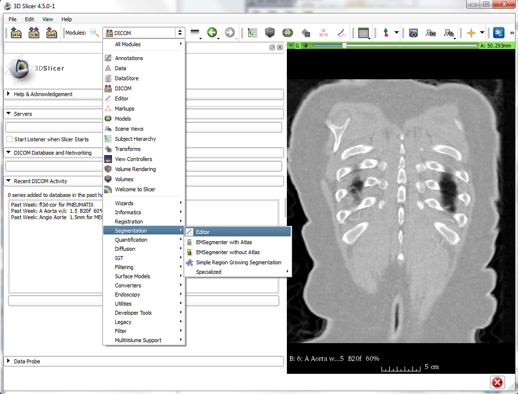
7. Open the segmentation editor (Modules > Segmentation > Editor) and select OK to choose the standard colour scheme for the label map.
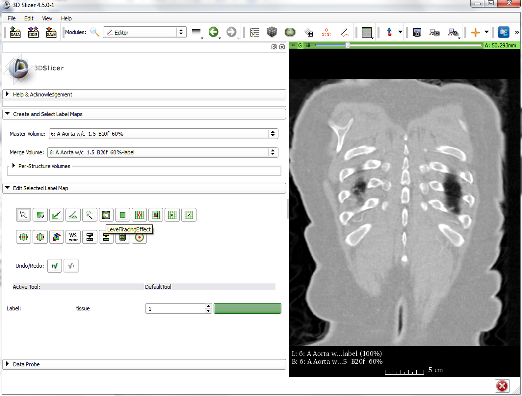
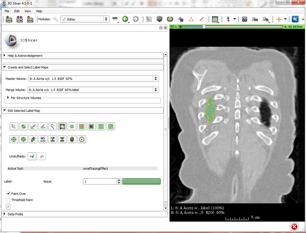
8. Select the Level Tracing Effect Tool in the ‘Edit Selected Label Map’ toolbox.
9. Use the tool to hover over the slice until the region of interest is outlined and left click to label the region.
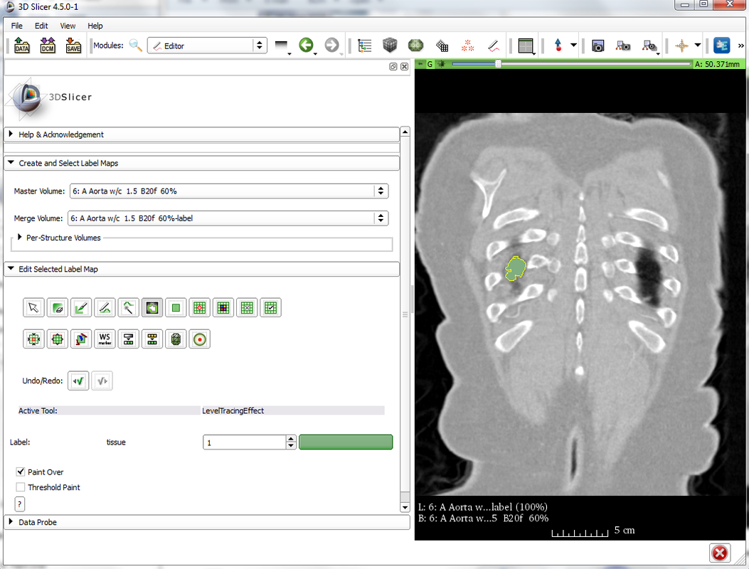
10. Use the slider or the scroller on your mouse to go to the next slice (A: 50.957 mm) and repeat the process – hover over the region of interest until it is outlined correctly, then left click to label this region.
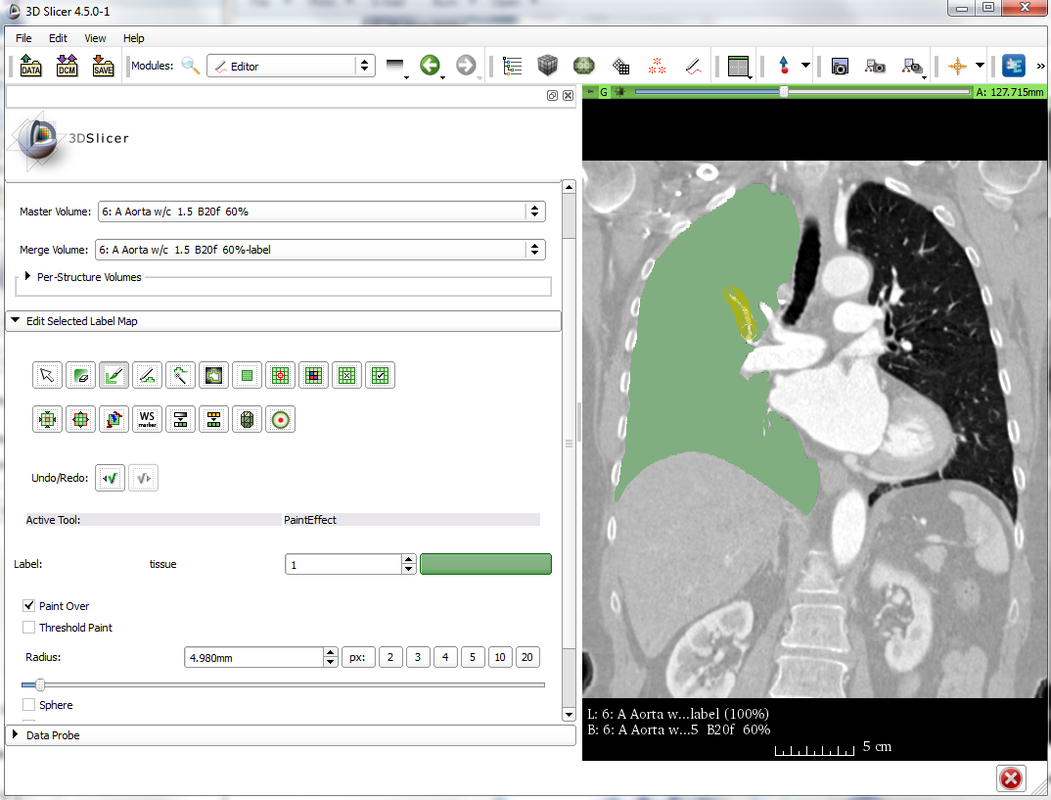
11. Repeat on each slice in the volume where the lung is visible (up to A: 211.824 mm), highlighting and labelling the lung in each slice. Allow some time for this stage. Ensure that this is accurate – the segmentation technique has a tendency to leak or to not highlight the entire region. Use the EraseLabel and PaintEffect tools to correct errors of this form by removing leaks and filling in holes.
12. Convert the label map on each slice into a 3D volume using the ModelMaker tool. (Modules > Surface Models > Model Maker)
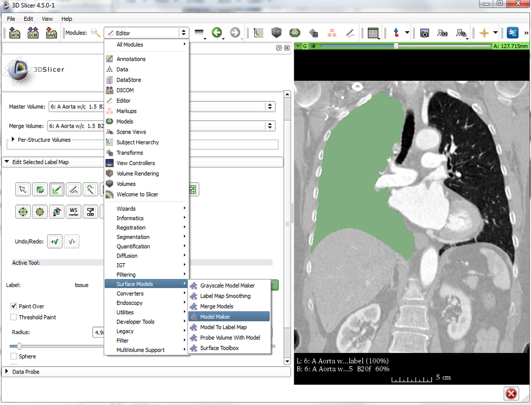
13. In the Model Maker module, ensure that the Input Volume is set to have the same name as your label. Change the Model Name to ‘lung’ or another suitable name, then select Apply to run the module.

14. Export the model as a stereolithography file (.stl). Click File then Save. Your model should be listed as a .vtk file (lung.vtk). Ensure that the box next to this file is ticked, the other files on the list do not need to be ticked at this point. Change the file format in the drop down menu to .stl, and choose a suitable directory where the model can be saved. Click Save to export the data.
15. Open Meshmixer (download from http://www.meshmixer.com/).
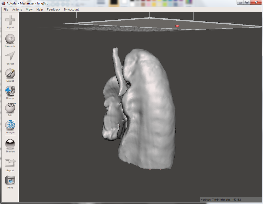
16. Import your model (File > Import > Select your model from the directory > Open). You should now be able to see your lung model. There will be some errors, which we can fix in this refinement stage. Basic commands: middle and left button on the mouse to translate, Alt and left click to rotate, scroll using middle button on mouse to zoom in and out.
15. Open Meshmixer (download from http://www.meshmixer.com/).
16. Import your model (File > Import > Select your model from the directory > Open). You should now be able to see your lung model. There will be some errors, which we can fix in this refinement stage. Basic commands: middle and left button on the mouse to translate, Alt and left click to rotate, scroll using middle button on mouse to zoom in and out.
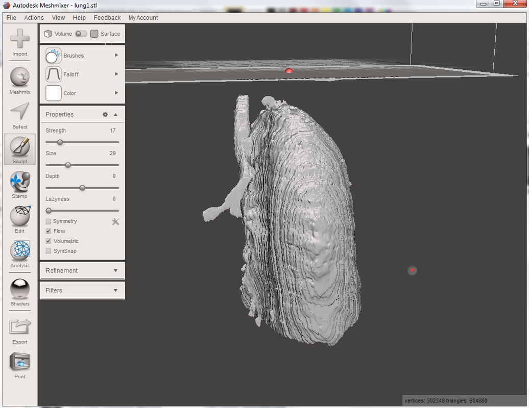
17. There are a number of filters that can be used to improve the quality of the model. Firstly, repair any holes using the inspector tool. (Analysis > Inspector > Auto repair all)
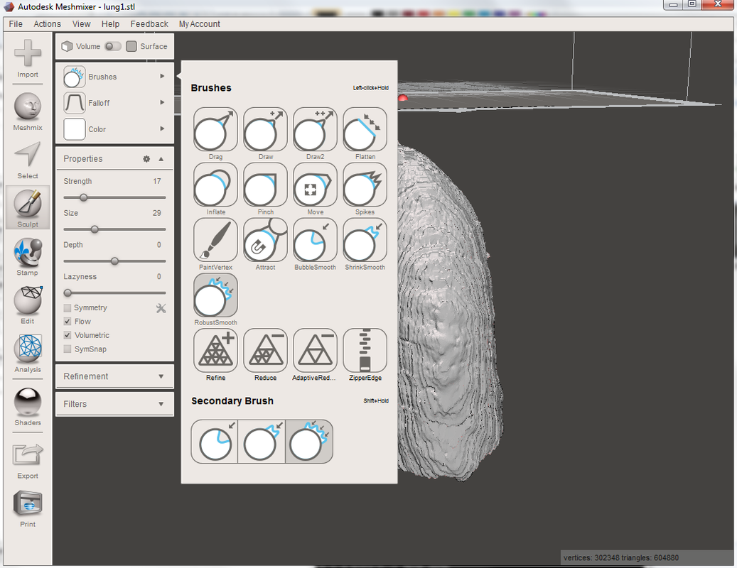
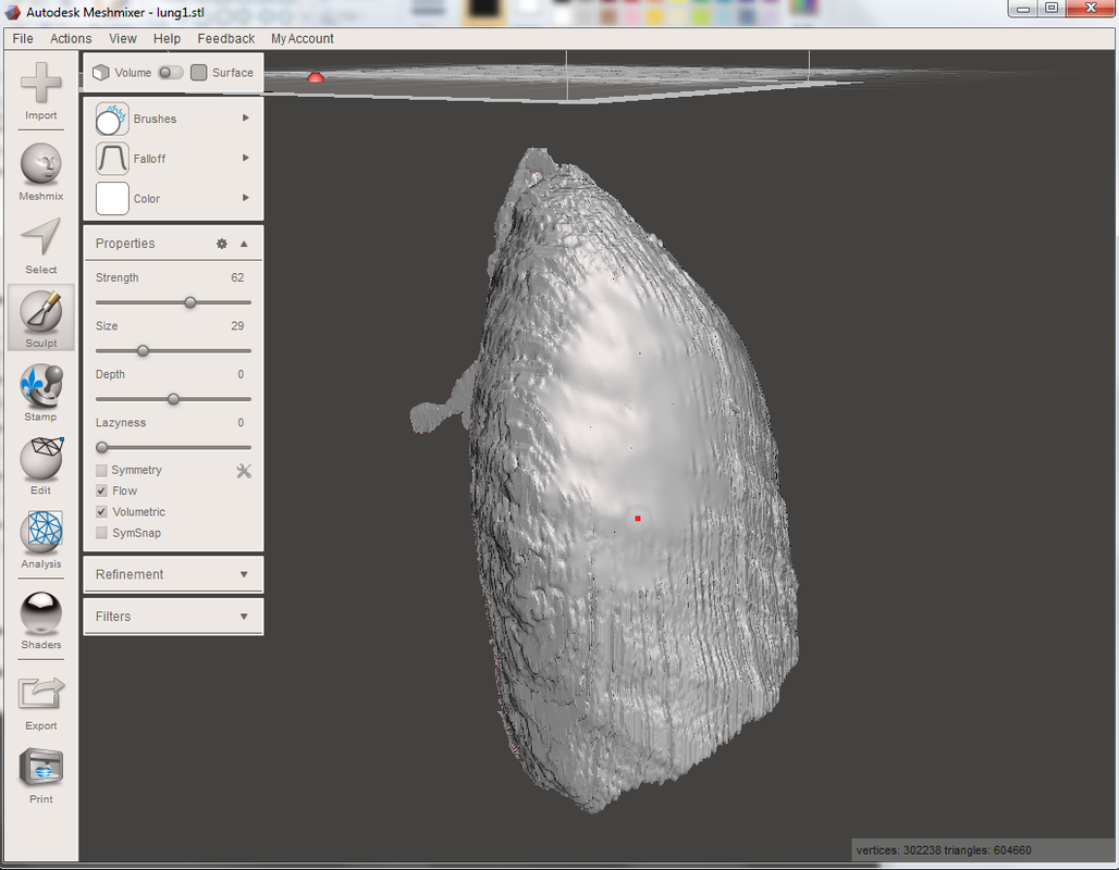
18. Then use the RobustSmooth tool (Sculpt > Brushes > RobustSmooth). You can set the strength, size and depth of the brush according to the application. It is best to start with a low strength and a larger size, then increase the strength and reduce the size as the structure becomes smoother. Move the brush over the surface of the model in a continuous way, not spending too much time on a particular area. You should be able to see that the surface becomes visually smoother as you do this. Make sure that you save multiple versions so that is possible to go back a step if you are not happy with the result at any stage.
18. Then use the RobustSmooth tool (Sculpt > Brushes > RobustSmooth). You can set the strength, size and depth of the brush according to the application. It is best to start with a low strength and a larger size, then increase the strength and reduce the size as the structure becomes smoother. Move the brush over the surface of the model in a continuous way, not spending too much time on a particular area. You should be able to see that the surface becomes visually smoother as you do this. Make sure that you save multiple versions so that is possible to go back a step if you are not happy with the result at any stage.
19. The Flatten and Inflate brushes are also useful if there are unphysical holes that need to be filled in – use inflate to fill the holes, then flatten and smooth so that the surface is continuous.
20. Once you are happy with the model, export the volume as a .stl file for final processing and printing. (File > Export > Save)
20. Once you are happy with the model, export the volume as a .stl file for final processing and printing. (File > Export > Save)